
Introduction to Walkoff
INTRODUCTION TO WALKOFF
How laser light propagates going from air into a material
Suppose we send two beams of light, each with a different unique color, through a transparent crystal. The light in each beam can also have different polarizations. Furthermore, suppose that these two beams are incident upon the crystal at the same location and going in the exact same direction. Once in the crystal, will they continue to go in the same direction—equivalently, are they still angularly aligned? Even if they remain angularly aligned, must they remain exactly on top of each other as they propagate through the crystal— equivalently, do they remain spatially aligned? In general, the answers are no and no. An angular change at an interface that is due to differences in wavelength is called angular dispersion. The purely spatial change that causes beams to move apart as they propagate through the crystal is called “walkoff”. Walkoff is less familiar to many people than dispersion. Both dispersion and walkoff are important for nonlinear optics. Here we’ll explain some of the differences between angular dispersion and walkoff, and then we’ll dig a little deeper into why walkoff matters for nonlinear crystals. An excellent and extensively detailed description of the topics discussed here can be found in Arlee Smith’s book: Crystal nonlinear optics: with SNLO examples. Albuquerque, NM, USA: AS-Photonics, 2018.
Dispersion and walkoff in a little more detail
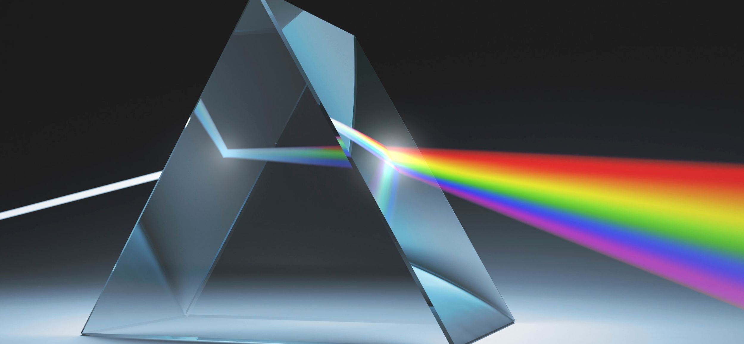
Dispersion angularly separates two beams of different colors that go through an interface, for example from air into a flat transparent glass or crystal. This is illustrated in Fig. 1. There is no deviation in the beam direction of either beam if they are transmitted exactly perpendicular to the glass’s surface, as shown in Fig. 2. That is a special case. At any other angle of incidence there will be angular dispersion, with a shorter wavelength of light bending (refracting) more at the surface than a longer wavelength of light. This is because the shorter wavelengths of light typically interact more strongly with materials than longer wavelengths so the refractive index is larger for shorter wavelengths. Dispersion is why prisms work and why there are rainbows.

Figure 2. Blue and red beams passing through glass at normal incidence. Neither beam’s direction deviates.
Figure 1. Blue and red beams passing through glass experience dispersion, a deviation in direction at the surfaces. The blue deviates more. This deviation is exaggerated beyond what is typical to allow it to be obvious in the drawing.

The Direction of a Light beam’s energy
Light is a form of energy. Walkoff is concerned with the direction of a light beam’s energy flow or power flow over time. The technical term for the direction and quantity of power flow is the Poynting vector, often represented by the letter “S” (symbols in boldface represent vectors). The Poynting vector is named after John Henry Poynting who described this concept in 1884. We can model a beam of light as a propagating electro-magnetic wave, and this wave can in part be characterized by its amplitude, wavelength, polarization, and frequency. All of these can also vary in time and space. For example, a beam can contain a spread of wavelengths, but for simplicity here we’ll consider beams with one wavelength. The wave’s direction and wavelength are characterized by a wave vector, usually represented by the letter “k”. The k vector points in the direction perpendicular to the wavefront.
The Poynting vector of light in air or in a vacuum points in the same direction as the wave vector, both exactly perpendicular to the light’s wavefronts, just as we might expect. In other words, k and S are parallel in air or vacuum. However, in anisotropic crystals (crystals that have structural directionality, like LBO and all nonlinear crystals), the Poynting vector is generally not perpendicular to the wavefronts. Energy may NOT flow exactly in the direction that the wavefronts seem to be going! This deviation in direction is called Poynting vector walkoff, or simply “walkoff” for short, and the angle the walkoff deviates from the k vector is often represented by the Greek letter ρ. When ρ is nonzero, it is still a small angle. It is often much less than a degree (1 degree is about 16 milliradians, mr), although in some crystals and orientations of the crystals ρ can be multiple degrees. However, even if less than a degree, walkoff matters. Fig. 3 shows walkoff for a beam in a crystal.
Figure 3. Blue and red beams propagate through an anisotropic (birefringent) crystal. The blue and red beams are assumed to have orthogonal linear polarizations. There may be walkoff at an angle ρ in the crystal, as shown. After the beams exit the crystal the direction of energy flow becomes parallel, meaning there is no more walkoff outside the crystal.

The polarization state of light affects walkoff
The polarization state of light affects walkoff and how the light goes through crystals. Walkoff occurs when the refractive index for polarized light in a crystal depends on the propagation direction. If the electric field from a light wave in a crystal interacts with the electrons in the crystal, the reaction of the electrons to that field may be constrained by the crystal, and the electrons may not move in exactly the same direction as the direction of the light’s electric field. This is what causes the walkoff in some crystals. There is no walkoff in glass or in air where the interaction with light is the same in all directions and for all polarizations. The exact equation for the angle ρ depends on the refractive index of the material and how that index changes with angle (see Note 1 below). Interestingly, walkoff doesn’t only occur with light. There is also walkoff for sound waves going through anisotropic materials such as striated sedimentary rock.
Which general direction does the Poynting vector deviate from the wave vector?
The Poynting vector is shifted from the k vector in the direction in the crystal that the polarized light would need to tilt in order to experience a lower refractive index. Here the refractive index is understood to be that for the polarized light’s electric field. The polarization of the light (the D field) is perpendicular to wave vector k; it is NOT parallel to k. Note that the wave vector and the polarization do not really change their tilt; this is just a way to qualitatively understand the direction of the Poynting vector compared to the k vector. Here is a harder question: Consider two beams of light propagating through space, as shown in Fig. 4. They have orthogonal linear polarizations and different wavelengths. Suppose also that we are told that the two beams started out directly atop each other, going in the same direction as each other. Is there some way to tell if they got separated by dispersion rather than by walkoff? If they have the same polarization then it was probably dispersion. But, with different polarizations, is there any way to know how they got separated? We’ll come back to this in Part II, stay tuned.
Note 1: The Poynting vector deviates from the k vector by an angle ρ given by ρ = arctan(-(1/n)(dn/dθ)). Here n is the refractive index which depends on the light’s wavelength, polarization and the angle (θ) of the polarization with respect to the crystal axes. See the reference to Arlee Smith above.
Figure 4. Two beams are shown, one blue and the other red. If these two beams originally overlapped, can you tell from looking at this drawing if they became separated by dispersion or by walkoff?

Walkoff matters when we use two or more beams of light to generate different wavelengths using nonlinear crystals.
A beam of green 532 nm light may be mixed with a beam of infrared 1064 nm light to generate ultraviolet 355 nm light. This is shown in Fig. 5, and the interaction is only efficient in generating UV light if the beams remain overlapped in the nonlinear crystal. When beams walk off from each other, the efficiency of nonlinear interactions suffers--it suffers a lot! The beam quality of the generated UV light may also be degraded. In addition, if we want to have two beams interact in a nonlinear material, we have to be careful not to have them unintentionally going in different directions for reasons like misalignments or angular dispersion. Typically in an example like the one above, generating 355 nm light, there are two steps. Starting with 1064 nm light, we generate some 532 nm light in a first nonlinear crystal. Next, we may mix the 1064 nm light with the 532 nm light to generate the 355 nm light. There can be walkoff in both of these two steps, further reducing the efficiency of infrared light to ultraviolet light.
Walkoff is not much of a problem if the crystals are very short, or if the beams are wide, or if both are true. With high peak power lasers, short crystals may give efficient nonlinear conversion. For example, consider a short 1 mm crystal length. The walkoff is just the product of the angle and the length, so if the walkoff angle is 10 mr (about 2/3 of a degree), then the actual walkoff is about 10 μm--ten microns. If the beam is 0.5 mm (500 microns) in diameter then this 10 μm of walkoff is a trivial effect compared to the beam diameter. However, what if the beams are 0.1 mm in diameter, and the peak powers are low so we want to use a long crystal, let’s say it is 25 mm long? Then the walkoff is 250 microns, which is 2.5 times greater than the whole beam diameter. This walkoff will ruin the beam overlap, cut the conversion efficiency, and degrade the beam roundness.
Figure 5. Second harmonic generation (SHG) followed by third harmonic generation (THG) is shown taking place in two different LBO crystals. Red represents the 1064 nm infrared light; green represents the 532 nm green light; and blue represents the 355 nm ultraviolet light.

If you enjoyed this article, stayed tuned for part two coming soon. Be sure to leave comments and let us know what topics you are interested in reading more about.
DR. WILLIAM GROSSMAN, AUTHOR
Will Grossman is a consultant retained by GAMDAN, and his role is to help our customers be more successful with nonlinear optics. His technical expertise includes laser design, nonlinear optics, and laser reliability. Dr. Grossman’s laser designs are used around the world in commercial products.More on the author can be found here.